| |
Further observation this again by isotape and we above wind the coil of modulator (input). It we twist as usually - toroidal. I wound 400 turns into two wires Of pev-0.e, i.e., came out two windings on 400 turns. This was made for the purpose of the expansion of the versions of experiment.
Now we place entire this system between two magnets. In my case these were barium-oxide magnets, the material of the stamp OF M22RA220-Y, it was magnetized in the magnetic field by tension not less than 640000 A/m, the sizes of 80kh'0khy' mm. magnets were undertaken from the magnetic-discharge diode pump NMD 0,16-1 or to it similar. Magnets are oriented "to the attraction" and their unit magnetic flux they pierce ferrite rings along the axis.
The work of thermoelectric generator consists of the following. It is original the tension of magnetic field inside the collector coil higher than outside because of the presence inside ferrite. But if we satiate core, then its magnetic permeability sharply will be lowered, which will lead to the decrease of tension inside the coil of collector. I.e. we should create this current in the modulating coil in order to satiate core. Up to the moment of saturating the core, the voltage on the collector coil will rise. With stress relieving with the manager of coil, the field strength again will grow, which will lead to the ejection of the reversed polarity at the output. Idea in the form presented is originated somewhere in the middle of February of 2004.
In principle, it is sufficient one modulator coil. The control unit is assembled according to classical diagram on TL494. upper according to diagram variable resistor changes the porosity of pulses from 0 approximately to 45% on each channel, lower - assigns frequency in the range approximately from 150 Hz to 20 kHz with the use of one channel, frequency, correspondingly, is reduced doubly. In the diagram is also provided the protection on the current through the modulator approximately into Д.
Parameters of the thermoelectric generator (measured by multimeter My-81):
winding impedance:
the inductance of windings without the magnets:
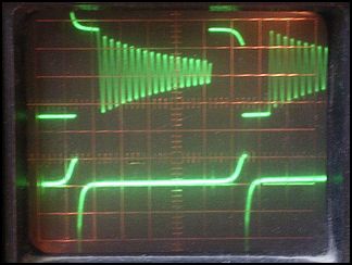
the inductance of windings with the established magnets: Experiment №1 (19.08.2004) Modulator coils are in series, came out as if bifilyarka. One channel of generator was used. The inductance of modulator 1,52 H, resistance - 22,7 Ohm the nourishment of the block of control here and throughout of 15 v, oscillogram were removed by the dual-trace oscillograph Of sy-shchshch. The first channel (lower ray) is connected through divider 1:20 (Cvx 17 pF, Rvx 1 M), second channel (upper ray) - directly (Cvx 40 pF, Rvx 1 M). Load in the chain of collector is absent. The first on that was inverted the attention: after the removal of pulse with the manager of coil, in it appear the resonance oscillations, and if the following pulse tax at the moment of reversed phase to resonance splash, then pulse at the output of collector appears at this moment. Also this phenomenon was noted, also, without the magnets, but to the much smaller degree. I.e., let us say so, in this case is important the slope of the change of potential on the winding. The pulse amplitude at the output could reach 20 v. however the current of such ejections is very small, and with difficulty it is possible to charge capacity to 100 F, connected to the output across the rectifying bridge. No other load output pulls. At the high frequency of the generator, when the current of modulator is maximally small, and the form of the voltage pulses on it preserves rectangular form, ejections at the output also be present, although the magnetic circuit is still very distant from saturation.
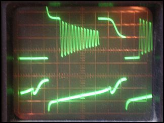
Conclusions: Thus far nothing essential it occurred. Simply let us note for itself some effects :) Here, I think, will valid note that there is, at least, one additional person - certain Sergey A, that experiments with the same system. His description was casually on www.skif.biz/phpBB2/viewtopic.php?.t=48&.postdays=0&.postorder=.asc&.start=15. I swear, we reached completely independently this idea:). On its studies how much far passed, to me it is not known, 4 with it it were not connected. But it also noted similar effects. Experiment №2 (19.08.2004) Modulator coils are disconnected and connected to two channels of generator, moreover they are connected counter, i.e., magnetic flux in the ring in the different directions alternately is created. The inductances of coils are given above in the parameters of thermoelectric generator. Measurements conducted as in the previous experiment. Load on the collector is absent. Lower in the oscillograms are represented voltage on one of the windings of modulator and current through the modulator (to the left) and also voltage on the modulator winding and voltage on the output of collector (to the right) with the different pulse duration. 4 thus far not to camp to indicate amplitudes and time characteristics, in the first place, 4 they not all preserved, but in the second place, this is not thus far important, until we attempt to qualitatively otsledit' the behavior of system.
I will explain the picture of stress on the modulator (upper ray). Stress was measured relative to plus of nourishment. Initial shelf - this is connection of modulator, further reverse splash with stress relieving and the excitation of oscillations because of the stray capacitance of key. Again splash, but collapsing - this works the second modulator. I will again focus attention, that the second modulator is included "counter". Following shelf - turning off of the second modulator and again oscillation. The second ray in the left figures - this is the current through the modulators. Current was measured by stress relieving from the low-resistance resistor, connected in series with the keys, i.e., potential on conclusion 16 tl494 (see oscillator circuit). In the figures to the right the second ray - voltage on the output of collector in the same regimes. On the first series of oscillograms it is evident that with the specific current of modulator the voltage on the output of collector attains maximum - this is intermediate moment before the passage of core into saturation, its magnetic permeability begins to fall. Turning off of modulator occurs at this moment and magnetic field is restored in the collector coil, which is accompanied by negative with a throw at the output. On the following series of oscillograms the pulse duration is increased, and core reaches complete saturation - a change in the magnetic flux ceases and voltage on output is equal to zero (decrease in the positive region). Reverse ejection with turning off of the winding of modulator further again follows. Now let us attempt to exclude magnets from the system, after preserving the operating mode.
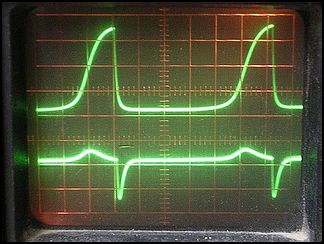
With the removal of one magnet, the amplitude of output was reduced almost 2. Let us note so that the frequency of oscillations was reduced, since the inductance of modulators increased. With the removal there is no second magnet, signal at the output. Conclusions: Similarly, idea, in that form as it was placed, it works. Experiment №3 (19.08.2004) Modulator coils are newly in series as into the 1- ohm experiment. Counter series connection of absolutely no effect gives. Nothing other 4 it expected:). They are connected as assumed. Is checked work, both in the no-load and with the load. Lower in the oscillograms they are shown the current of modulator (upper ray) and the stress of output (lower ray) with different pulse durations on the modulator. Here and throughout I decided to tie to the current of modulators as to that most being suitable in the role of reference signal. Oscillograms were removed relative to common wire. First 3 figures - in the no-load, the latter - with the load.
Figures from left to right and from top to bottom: 1) the short pulse duration, 2) an increase in the duration with the approach to the region of saturation, 3) optimum duration, complete saturation and maximum output voltage (with the idling), 4) the last operating mode, but with the connected load. Incandescent lamp 6,3 v served as load, 0,22 A. svecheniyems this cannot be certainly named...:)
The measurements of power in the load were not conducted, interestingly another:
Conclusions: I do not know that also to think... Consumption was reduced by 0,3%. Generator itself without the thermoelectric generator consumes 18,5 mA. Possibly, load indirectly through a change of distributing the magnetic field influenced the inductance of modulators. Although, if we compare the current oscillograms through the modulator in the no-load and with the load (for example, with the paging through hither and thither in AccDSee), then it is possible to note the weak obstruction of the top of peak with the work with the load. However, an increase in the inductance would lead to the decrease of the width of peak. Although all this is very spectral... Experiment №4 (20.08.2004) The purpose is set: to obtain peak yield per what there is. In the past experiment it were rested into the frequency limit, at which the optimum pulse duration with a maximally possible level of filling of pulse ~45% (porosity it was minimum) was ensured. So that it was necessary to decrease the inductance of the modulator winding (earlier they were connected two consecutively),; however, in this case it is necessary to increase current. So that now modulator coils are connected separately to both outputs of generator as 2- m experiment; however, this time they are connected in one direction (as it is indicated on the fundamental oscillator circuit). Oscillograms in this case changed (they were removed relative to common wire). They appear much more pleasant:). Furthermore, we now have two windings, which work alternately. Means with the same maximum pulse duration we we can double frequency (for this diagram). The specific regime of the work of generator on the maximum brightness of lamp at the output is selected. And since usually, immediately let us switch over to figures...
Here we to the left clearly see an increase in the voltage on the winding of modulator in the operating cycle of the second (second half-period, logical "0" in the right oscillogram). Ejections with turning off of modulator into 60 volts are limited to the diodes, which form part of field keys.
Load - entire the same lamp 6,3 in, 0,22 a. I again is repeated picture with the consumption...
We again have a reduction in the consumption with the load connected to the collector. Measurements certainly on the threshold of instrument accuracy, but, nevertheless, repetition 100%. Power in the load was about 156 mW at the entrance - 9,15 W. But thus far no one said about the "perpetual motion machine":) Here it is possible to admire to the burning lamp:
Conclusions: Effect it is present. What we will be able from this to obtain - time will show. On what should be focused attention? The first, to increase a quantity of turns of collector, possibly, after adding another vapor of rings, and is better to select the optimum dimensions of magnetic circuit. Who would study calculations? ;) Possibly, magnetoareode makes sense to increase magnetic permeability. This must increase a difference in the tensions of magnetic field inside and outside the coil. To simultaneously decrease the inductance of modulator. It seemed also that the clearances between the ring and the magnet were necessary, so that, let us say so, there would be place for the bending of unit magnetic flux with the change of the properties of medium - magnetic permeability. However, in practice this leads only to the decrease in the voltage on output. At the present moment the clearances are determined by 3 layers insulating tapes and with the thickness of modulator winding, by rule of thumb this is maximum on 1,5 mm from each side. Experiment №4.1 (21.08.2004) The previous experiments were conducted on the work. Brought the control unit and "transformer" home. The same collection of magnets in me had long ago been dragged along and house. It gathered. It revealed with the surprise that I can raise another frequency. Apparently my "domestic" magnets were only more feasible, in consequence of which the inductance of modulators was reduced. Radiators has already been heated more strongly; however, the current of the consumption of diagram was 0,56 A and 0,55 A without the load and with the load respectively, with the same nourishment 15 By v. vozmozhno, the through current through the keys occurred. In this diagram at the high frequency such is not excluded. To the output connected halide lamp to 2,5 v, 0,Ea. In the load it obtained 1,3 in, 200 mA. Altogether entrance 8,25 W, output 0,26 W - EFFICIENCY 3,15%. But note, in addition without the expected traditional influence on the source! Experiment №5 (26.08.2004) It is assembled new converter (version 1.2) on the ring with the larger permeability - MY0000NM, sizes the same: O40x.O25x11 mm. Unfortunately, ring was only one. In order to accomodate more than turns on the collector winding, wire is undertaken to poton'she. Altogether: the collector of 160 turns by wire O 0,3 and so two modulators on 235 turns, so by wire O 0,3. But is so found new power unit azh to 100 v and by the current to 1,2 A. napryazheniye of nourishment also can play role, since it ensures the speed of the growth of the current through the modulator, and that, in turn, the rate of change in the magnetic flux, which is directly connected with the amplitude of output voltage. Thus far by something to measure the inductances and to imprint pictures. Therefore without the excesses I will present naked numbers. Several measurements were carry ouied with the different supply voltages and the regimes of the work of generator. Some of them are given below. without the output in complete saturation
Entrance: 20 V X of 0,3 A = of 6 W
Entrance: 10 V X of 0,6 A = of 6 W
Entrance: 15 V X of 0,5 A = of 7,5 W with complete saturation
Entrance: 15 V X of 1,2 A = of 18 W Conclusions: It turned out that in the regime of complete saturation, goes the decrease EFFICIENCY, since the current of modulator sharply grows. The optimum mode of operation (on THE EFFICIENCY) it was possible to dostich' with the voltage of supply 15 v. of loading effect on the power source not discovered. For the given 3rd example with EFFICIENCY 4,2, the current of diagram with that connected with the load must increase approximately on 20 mA, but increase so it is not fixed. Experiment №6 (2.09.2004) The part of the turns of modulator for the purpose of an increase in frequency and decrease of clearances between the ring and the magnet is removed. Now we have two windings of modulator on 118 turns, wound into one layer. Collector is left without the changes - 160 turns. Furthermore, are measured the electrical characteristics of new converter.
The parameters of thermoelectric generator (version 1.21), it is measured by multimeter My-81:
winding impedance:
the inductance of windings without the magnets:
the inductance of windings with the established magnets: I present below the results of two measurements of the work of thermoelectric generator in the different regimes. The modulation frequency is above with the more high voltage of nourishment. In both cases the modulators are in series.
Entrance: 15 V X of 0,55 A = of 8,25 W
Entrance: 19,4 V X of 0,81 A = of 15,714 W Conclusions: First and saddest. After the introduction of changes in modulator, is fixed an increase in the consumption with the work with the new converter. In the second case the consumption grew approximately on 30 mA. I.e. without the load consumption was 0,78 A, with the load - 0,81 By a. pomnozhayem by those feeding 19,4 v we will obtain 0,582 W - that power itself, that they removed from the output. However, I will be repeated with the entire responsibility, which earlier than similar was not observed. With the connection of load in this case clearly is outlined the steeper growth of the current through the modulator, what is the consequence of the decrease of the inductance of modulator. With which this is connected, until it is known. And another spoon of tar. I fear, in this configuration THE EFFICIENCY will not be succeeded in obtaining more than 5% because of the weak overlap of magnetic field. In other words, saturating core, we weaken field inside the collector coil only in the region of the passage of this core itself. But unit magnetic flux going from the center of the magnet through the center of coil overlap in no way. Moreover, the part of unit magnetic flux of "those extruded" from the core with its saturation also goes around the latter from the inside of ring. I.e. thus is modulated only the small part of the magnetic flux PM. It is necessary to change the geometry of entire system. Possibly, it follows to expect a certain increase EFFICIENCY, using annular magnets from the dynamic loudspeakers. So does not release thought about the work of modulators in the regime of resonance. However, under the conditions of saturating of core and, correspondingly, constantly changing inductance of modulators this to make is not very simple. Studies continue... If you want to discuss, you go to the "absorbed forum", my is no Armer. Or write on armer@mail.ru, but I think, it is better into the forum. Dragons' Lord : First of all, the enormous thanks Armer'u for the fact that the report about the carried out experiments with the splendid illustrations granted. I think, soon us expect the new works of Vladislav. But thus far I will express its thoughts to the calculation of this project and its possible way of improvement. I propose to change oscillator circuit as follows:
Instead of the flat external magnets (plates) it is proposed to use annular magnets. Moreover, the inside diameter of magnet must be approximately equal to the analogous diameter of the ring of magnetic circuit, and the outside diameter of magnet is greater than the outside diameter of the ring of magnetic circuit. In what the problem of low EFFICIENCY? Problem in the fact that the unit magnetic flux, displaced from the magnetic circuit as before intersect the area of the turns of the secondary winding (they wring out and they are concentrated in the central region). The relationship of rings indicated creates asymmetry and it constrains the large part of unit magnetic flux, with the saturated to the limit central magnetic circuit, to go around it on THE EXTERNAL space. In the interior of unit magnetic flux it will be less than in the base version. In general, this "illness" cannot be completely cured, on the previous using rings. As to raise overall EFFICIENCY is said below. Also it is proposed to use the additional external magnetic circuit, which concentrates line of forces in the operating region of device, making it more powerful (it is here important not to pereborshchit', since it is utilized idea with complete saturation of central core). It is structural, external magnetic circuit is the tochennye ferromagnetic details of axisymmetrical geometry (something like the flanged tube). The horizontal parting line of upper and lower "cups" you see on the picture. Or, this there can be the discrete independent magnetic circuits (clamps). Further it is worthwhile to think above the improvement of process from an "electrical" point of view. It is understandable, the first that is necessary to make, this to swing the primary circuit into the resonance. Indeed us lacks the harmful opposite effect from the second chain. It is proposed to use current resonance for the intelligible reasons (indeed purpose, to satiate core). The second observation, possibly, not such obvious to the first view is proposed as the secondary winding to use not a standard solenoid coil of coil, but to make several flat bifilar coils of Tesla and to place them on the outside diameter of magnetic circuit the "foliated patty", after connecting consecutively. In order to generally remove existing minimum interaction with each other in the axial direction of adjacent bifilar coils, it is necessary to connect them so THROUGH ONE, after returning with the latter to the second (repeated use of sense of bifilar coils). Thus, due to the maximum difference of potential in two adjacent turns the stored energy of second chain will be maximally possible, which by an order exceeds version with the usual solenoid. As can be seen from diagram, considering that the "patty" from bifilyarok has sufficiently decent extent in the horizontal direction, it is proposed to twist pervichku not on top of vtorichki, but under it. Directly to the magnetic circuit. As 4 already he said, using rings, it is not possible to overcome the specific limit EFFICIENCY. And I assure, that of sverkhedenichnost'yu there and it does not smell. The unit magnetic flux extruded from the central magnetic circuit will go around it along surface itself (on the shortest path), thus, on the previous intersecting the area, limited by the turns of vtorichki. The analysis of construction constrains to forego the current circuit design. Central magnetic circuit WITHOUT the opening is necessary. Let us glance at the following diagram:
Basic magnetic circuit is collected from the separate plates or the rods of rectangular cross section, and represents parallelepiped. Pervichka places directly to it. Its axis is horizontal and according to diagram looks on us. Vtorichka, the as before "foliated patty" from bifilyarok of Tesla. Now let us note that we introduced the additional (second) magnetic circuit, which represents "cups" with the openings in their Donets. Clearance between the edge of opening and the basic central magnetic circuit (primary coil) must be minimal, in order to effectively intercept the extruded unit magnetic flux and to draw off them to itself, without giving to them to pass through the bifilars. Certainly, it must be noted that magnetic permeability of the central magnetic circuit must be by an order higher than auxiliary. For example: central parallelepiped - 10000, "cups" - 1000. In normal (not saturated) state central core, due to its larger magnetic permeability, will draw unit magnetic flux into itself. But the now most interesting;) . Attentively let us get accustomed, however, that we obtained?... But we obtained most usual MEG, only in the "unfinished" version. In other words, I want to say that the classical performance of generator MEG v.4.0 in several times passes our best diagram, in the form of its possibility redistributing the unit magnetic flux (rocking "swings") to remove useful energy on entire cycle of its work. Moreover, from both arms of magnetic circuit. In our case we have single-arm construction. Half of available EFFICIENCY it is not simply utilized.
I express hope, that Vladislav in the nearest time will conduct the experiments above MEG v.4.0, especially because such machine (in execution v.3.0) he already has;). And certainly, it is necessary to compulsorily use current resonance on the primary controlling coils, established not directly on the arms of magnetic circuit, but on the ferrite insert- plates, it is perpendicular to the same (in the break of magnetic circuit). Report, on the entering to me, 4 I will immediately make up into pages and will grant to our readers.
| |||||||||||||||||||||||||||||||||||||||||||||||||||||||||||||||||